Welcome to the guide that will demystify the Finite Element Method (FEM) for analysis! Whether you’re a student, an engineer, or a professional looking to enhance your analytical toolkit, this guide will provide step-by-step guidance to understand and apply FEM effectively. We’ll cover practical examples, actionable tips, and troubleshooting solutions to help you master this powerful analytical technique.
Introduction to Finite Element Method (FEM)
Finite Element Method is a powerful computational technique used to solve complex physical problems by dividing them into smaller, simpler parts called finite elements. It is widely used in engineering, physics, and other fields to analyze stresses, strains, heat transfer, fluid flow, and more. Understanding FEM not only opens up a new dimension in your analytical capabilities but also provides a deeper insight into how different systems respond to various forces.
Why You Need to Understand FEM
If you’ve ever struggled with intricate mathematical models or needed to validate your physical simulations, FEM could be your game-changer. It provides a systematic approach to break down complex problems into manageable pieces, allowing you to solve partial differential equations that describe physical phenomena. FEM offers greater accuracy and flexibility, especially when dealing with non-uniform geometries, complex boundary conditions, or nonlinear materials properties.
However, diving into FEM can be daunting, especially for beginners. That’s why this guide focuses on addressing your pain points with practical solutions, actionable advice, and real-world examples.
Quick Reference Guide
Quick Reference
- Immediate Action Item: Begin by understanding basic principles of FEM such as discretization, element types, and mesh generation.
- Essential Tip: Utilize software tools like ANSYS, Abaqus, or FreeFEM which offer intuitive interfaces for FEM modeling and simulation.
- Common Mistake to Avoid: Overlooking mesh quality and element type, which can lead to inaccurate results.
How to Get Started with FEM: Step-by-Step Guidance
Getting started with Finite Element Method can be overwhelming at first, but breaking it down into manageable steps makes the process straightforward and clear.
Step 1: Understand the Basics
Before diving into complex simulations, it’s crucial to understand the basic principles of FEM:
- Discretization: Break down the entire geometry into smaller, manageable parts known as finite elements.
- Element Types: Familiarize yourself with various element types, such as 1D (lines), 2D (triangles, quadrilaterals), and 3D (tetrahedra, hexahedra) elements.
- Mesh Generation: Learn how to create a mesh, which is the arrangement of these elements covering the geometry.
Step 2: Choose the Right Software
Selecting appropriate software is essential for effective FEM analysis. Here are some popular options:
- ANSYS: Widely used for structural, thermal, and fluid analyses.
- Abaqus: Known for its capability in advanced structural and material simulations.
- FreeFEM: An open-source option for those who prefer a free software solution.
Start with a user-friendly software that matches your intended application. Many of these software tools offer tutorials and detailed manuals to get you started.
Step 3: Model Creation
Modeling is a critical phase in FEM:
- Geometry Creation: Start by creating the geometry of your model. Most FEM software tools offer CAD integration to import or create detailed geometries.
- Mesh Generation: Generate a mesh for your model. Pay attention to mesh density and element type to ensure accurate results. Too coarse a mesh might miss details, while an overly dense mesh can make computation cumbersome.
- Material Properties: Define the material properties for your elements, including density, elasticity, viscosity, and any other relevant properties.
Step 4: Applying Boundary Conditions
Boundary conditions describe how the model interacts with its environment:
- Displacement Boundary Conditions: Specify fixed or movable parts of the model.
- Load Boundary Conditions: Apply forces, pressures, or temperature changes to simulate real-world scenarios.
- Contact Conditions: Define interactions between different parts of the model.
Step 5: Running the Simulation
With your model, mesh, and boundary conditions set, you’re ready to run the simulation:
- Execute the Analysis: Initiate the solver to compute the response of the model to the applied conditions.
- Review Outputs: Examine results like deformation, stress, and temperature distribution. Most software provides graphical representations to help visualize these results.
- Validate Results: Compare your simulation results with theoretical values or experimental data to ensure accuracy.
Step 6: Post-Processing
Post-processing involves interpreting and presenting the simulation results:
- Result Visualization: Use visualization tools to create plots, contour maps, and animations to understand the model’s behavior.
- Data Export: Export results in various formats for further analysis or reporting.
Deep Dive into FEM Software: ANSYS Example
Let’s delve into a practical example using ANSYS, one of the most powerful and widely-used FEM software tools. We’ll go through a step-by-step example of how to perform a structural analysis of a cantilever beam.
Step 1: Geometry Creation
Open ANSYS Workbench and create a new project. Select the “Design Model” module for geometry creation. Use the drawing tools to define the shape of the cantilever beam, specifying dimensions like length, width, and thickness.
Step 2: Mesh Generation
Navigate to the “Mesh” module and generate a mesh for your beam geometry. Use the meshing tools to control the mesh density. A finer mesh increases accuracy but also computation time.
Step 3: Define Material Properties
In the “Material” module, define the properties of the beam material. Common properties include Young’s modulus, Poisson’s ratio, and density. For instance, if you’re using aluminum, input its specific material constants.
Step 4: Apply Boundary Conditions
Switch to the “Solution” module and apply boundary conditions:
- Fixed Support: Apply a fixed support at the root of the cantilever beam to simulate the support condition.
- Forced Load: Apply a vertical force at the free end to simulate a load.
Step 5: Run Simulation
Execute the solver by clicking on “Solve.” ANSYS will perform the finite element analysis to compute the response of the beam to the applied load.
Step 6: Post-Processing
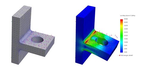
After the simulation completes, navigate to the “Graphics” module to visualize the results:
- Deformation: Examine the deformation plot to see how the beam bends under the load.
- Stress Distribution: Use contour plots to understand the stress distribution across the beam.
Practical FAQ
What is the most common mistake when setting up FEM simulations?
One of the most common mistakes is overlooking the importance of mesh quality. Poor mesh density or improper element types can lead to inaccurate results. Always validate your mesh by checking if finer meshes lead to similar results, indicating a well-converged solution.